Ecco le foto riprese dal video della telecamera sull’elmetto, il danno è evidentissimo lungo tutta la corona circolare.
Penso non ci siano dubbi si possa trattare di pitting…
Provo a buttare lì una ipotesi tanto per parlare… non potrebbe essersi trattato di un micrometeorite ? Mi spiego meglio… un piccolo micrometeorite che è entrato all’interno del SARJ ed è rimasto incastrato fra gli ingranaggi ? Capisco che sembri un’ipotesi poco plausibile ma francamento se questo problema affligge soltanto uno dei due SARJ non potrebbe essere? Certo, un più prosaico errore di montaggio è molto più naturale ma quello che mi fa dubitare è che il problema sia sorto soltanto adesso… ![]() Speriamo che le varie ispezioni fatte e quelle previste in futuro riscano a far comprendere ai tecnici della NASA quello che è successo e possano aiutarli a trovare il modo per rimediare.
Speriamo che le varie ispezioni fatte e quelle previste in futuro riscano a far comprendere ai tecnici della NASA quello che è successo e possano aiutarli a trovare il modo per rimediare.
Boh… francamente non riesco a pensare a molte cause… il meteorite penso che non riesca a “ficcarsi” in quella scanalatura senza lasciare buchi o danni ben visibili…
Potrei ipotizzare anche un difetto nel trattamento superficiale… ma sarebbe abbastanza grave…
Potrebbe sempre essere possibile un difetto nei trattamenti vari che il metallo ha subito durante le varie fasi della costruzione del giunto del SARJ, che poi esposto all’ambiente spaziale, lentamente si è acuito con il tempo… ![]()
Dopo un’improbabile brainstorming di un paio di elementi del forum che a certe ore non avevano nulla di meglio da fare che arrovellarsi per internet alla ricerca di maggiori info, siamo riusciti (forse) a ricavare qualche cosa di più dalla semplice sigla “1505 Nitrude” della lega dei frammenti rinvenuti nel giunto.
Dovrebbe trattarsi di una lega d’acciaio della famiglia 15xx Plain Carbon con il 0,05% di carbonio e una percentuale di Manganese compresa fra 1 e 1.65% con trattamento superficiale di indurimento a nitrurazione.
Ora c’è però bisogno di qualcuno un po’ più esperto in materiali per capire come possa presentarsi in una lega di questo tipo del pitting e da cosa potrebbe essere provocato…
Passiamo la palla… ![]()
Spacewaaaalker!!! [-o<
A completare la panoramica sul SARJ in questione inserisco questi 4 schemi che illustrano il funzionamento del meccanismo e una foto del reale:
Con breve spiegazione del funzionamento delle componenti principali interessate dal problema (preso dal presskit della STS-115 che ha portato il segmento gemello P3/P4):
Solar Alpha Rotary Joint
The Solar Alpha Rotary Joint (SARJ) enables the new outboard solar arrays to always point to the sun by rotating like a Ferris wheel. The port SARJ on P3/P4 provides tracking for the P4 and P6 solar arrays once P6 is relocated to P5 on the STSâ€120 mission. The starboard SARJ for the S3/S4 arrays, to be delivered on STSâ€117, will provide tracking for the S4 and S6 solar arrays once S6 is installed on the STSâ€119 mission. The SARJ can rotate 360 degrees clockwise and counterclockwise. The SARJ also provides the structural interface between the P3 or S3 and P4 or S4 elements. It includes hardware to route power and data through the rotating SARJ interface to the outboard truss segments.
Race Rings
The SARJ includes an inboard and an outboard race ring, which provide the structural connection between the P3 and P4 elements. Along the circumference of each race ring are gear teeth that mesh with the drive lock assembly (DLA) pinion gear to rotate the SARJ. The outboard race ring is used by the DLA for rotating the SARJ.
Trundle Bearings
The 12 equallyâ€spaced trundle bearings hold the SARJ inboard and outboard race rings together. Each trundle bearing is fixed to the inboard race ring and is clamped onto the outboard race ring with a roller interface to llow for SARJ rotation. There are three rollers on the trundle bearing that interface with the outboard race ring; the inner and outer upper rollers and the center roller. Each roller consists of two bearings: the primary and journal bearings. The primary bearing rotates. If the primary bearing seizes up, the journal bearings will begin rotating. The journal bearing is designed to operate for about 30 days. There are microâ€switches in the trundle bearing that allow the ground to know if the journal bearing is rotating.
Drive Lock Assembly
Two Drive Lock Assemblies (DLAs) are responsible for rotating and locking the SARJ. Each DLA includes the engageâ€disengage mechanism (EDM) motor, drive motor, pinion gear, lock rack and two follower arms. The EDM motor is a stepper motor that pivots the lock rack and pinion gear about the lock/engage pivot point to the desired position. The DLA positions are locked, engaged and neutral. For the locked position, the lock rack is in contact with the race ring gear teeth to prevent the SARJ from rotating. For the engaged position, the DLA pinion gear is meshed with the race ring gear to rotate the SARJ with the drive motor. In the neutral position, neither the lock rack nor pinion gear is engaged to the race ring gear. The follower arms, which are of the same design as the trundle bearings, are used to secure the DLA to the race ring.
Rotary Joint Motor Controller
The two rotary joint motor controllers (RJMCs) are mounted on the structural ribs of the inboard race ring and control the operation of the DLA motors via commands from the 3 multiplexers/demultiplexers (MDMs). Each RJMC has two heaters and a resistive thermal device sensor monitored by the P3 MDMs. The RJMC supplies and receives voltage signals from the resolvers on the Utility Transfer Assembly to determine the position f the SARJ (resolver A is connected to RJMC 1, resolver B is connected to RJMC 2). For SARJ outboard operations, one RJMC is moved to the outboard race ring.
In allegato gli schemi e il presskit che illustra il funzionamento di tutto l’ITS S3/S4.
Altro materiale da una presentazione durante STS-120
Finalmente vere foto del danno, nei link qui sotto in HQ:

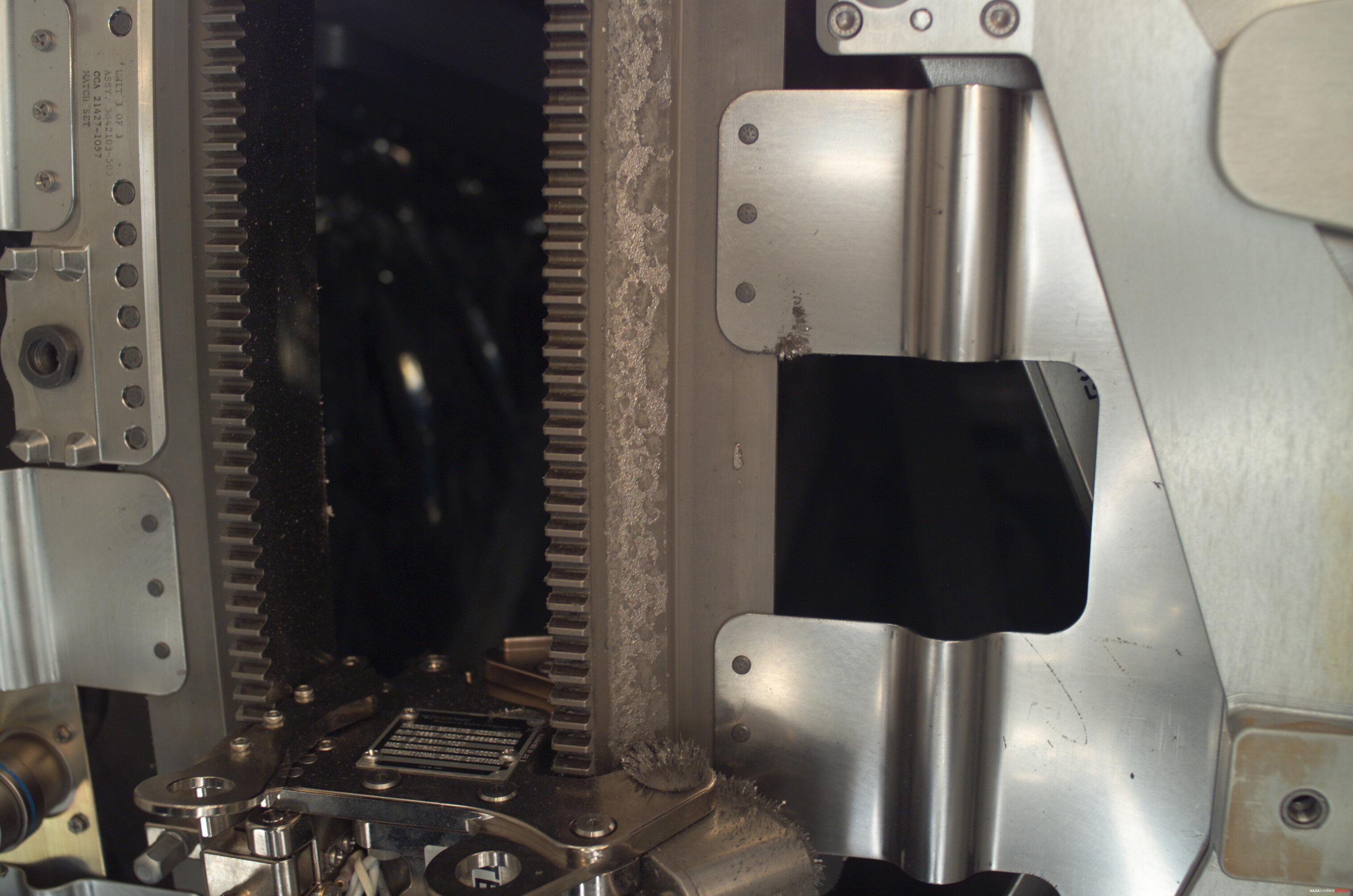

Guardate in basso alla cremagliera di destra come è ben visibile la “limatura” magnetizzata provocata dal danno.